

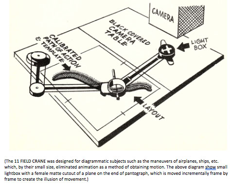
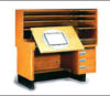
THE CAMERA section of the manual continues with the 11 FIELD CRANE, which is a fascinating Ub Iwerks designed camera stand that permitted “the use of other kinds of material than could not be used on the multiplane crane. The field was 2 ½ times as large as the 5 F [Acme 10.5F](1).” The 11 FIELD CRANE is not designed to handle regular animation, there are no pegs or peg bars. Movement is achieved by moving material, i.e. a light box or models, over the camera table. This camera crane was solely used for the “diagrammatic subjects such as the maneuvers of airplanes, ships, etc. which, by their small size, eliminated animation as a method of obtaining motion.” This Iwerks invention used either bottom or top lighting allowing for female masks to be illuminated from below or 3-demensional models against flat black or painted backgrounds to be lit from above.(2)(3)
The text states that, “material illuminated from below or “BACKLIT,” consists of female masks entirely. A female mask is one where the material to be photographed is silhouetted clear, on a blackened cel or portion of cel.”(4) The blackened portion of the cel, from the authors experience, typically received two coats of paint to make sure that it was in fact opaque when bottom lit. Sometimes when the first coat of paint is applied to a cell, there will be varying density or thicknesses to the paint based on the brush technique. For top light, that cel may look perfectly fine but with bottom light on there will be light visible in the areas where the paint layer may have gotten too thin.(5) The female masks on cel were mounted in various ways against large sheets of black paper depending on how the mask was going to be used. The masks could also be made out of metal as well. The metal masks, made in the Studios’ Machine Shop, were “more accurate than cels for very small material” this was especially true if the mask was to be used multiple times. “This was done to achieve certain effects moving in more or less straight lines—dotted lines, etc.”(6)
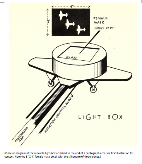
Another method used was the “moveable light-box,” which was a small, circular metal holder that held a small female mask and “traveled over the camera table in any desired direction.” The metal holder is lit from within and no other camera lights are used to illuminate the camera table. The result is the silhouette image created by the female mask and is the only thing exposed onto film or photographed. Based on the same principle as the pantograph, the light-box was connected to the end of a system of pulleys and arms. “The camera set-up consists of two large tables locked together, each somewhat larger than an 11 field (Acme 26.25F)(7). One of the tables is the actual camera table and the other table has the pantograph mounted to it with the calibrated path of action on a fixed layout. A crosshair cup, at the center elbow of the longer arms of the pantograph, is used to incrementally move the light-box frame by frame. “The operator guides the cup with pin over the layout and a couple of feet away” outside the camera view as the “female mask of the airplane or ship, goes thru exactly the same maneuvers.”(8) The other interesting thing about the crosshair cup is that it can be rotated which in turn rotates the light-box at the end of the pantograph arm allowing for the wings of an aircraft to remain at a right angle to the flight path being created.
The quality of the animation is dependent on the accuracy of the path of action layout. For the 11 FIELD CRANE, all of the work had to be done on paper 25-inches by 32-inches.(9) The 11 Field area, which measured 19.688-inches by 26.250-inches, easily fit with in that size paper.
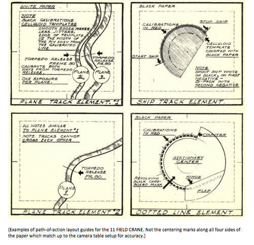
To make the layout diagram for the path of action, first accurate registration marks were needed centering north, south, east and west on the sides of the paper. The centering marks match corresponding marks on camera table setup. The layout example above includes the elements for the entire scene, in this case, the path-of-action for the ship, the dotted course line behind it and the paths of the attacking planes (a separate path for each plane). It was okay to have more than one path on a layout chart provided that the paths did not overlap. Creating these charts was critical to the outcome of the animation because, “as moves the guide cup [with crosshairs], so moves the little clear plane, mounted on the light box at the other end of pantograph arm.”(10)
Incidentally, there was a device that made the calibration marks called, what else— a “mechanical calibrator.” It was a self-inking roller that had eleven different interchangeable calibration scales ranging from .02 to .10. The text notes that it is about the “size of Junior’s locomotive, and almost as much fun to play with.” So rather than having to make the tic marks by hand with a pencil and ruler, the scales would be rolled on with ink. “The marks produced by the mechanical calibrator are only 3/8” across; consequently, calibrations on curves must be elongated for accurate crosshair registration.”(11) This is why paths of action could not cross or even come that close in proximity to one another. The mechanical calibrator produced calibration marks fast and perfectly on straight or curved paths, provided that the curves are not too sharp.(12)
It is important to make note of the calibration of the pantograph guide cup. The manual states that “the guide cup has either two pins, spaced along the north/south crosshair, or one pin at the intersection. The two pins are used when moving along a straight line but will naturally err on curves, so then the center pin is substituted. This center pin occupies the point of exact registry on the guide drawing, so when it must be used, registration is maintained by the crosshairs, north/south and east/west.”(13) The explanation makes more sense when you actually have the pantograph setup right in front of you and can see the various components firsthand.
Finally, there are some notes at the end of the 11 FIELD CRANE section that gave pointers for better efficiencies on the equipment. Again, it was all about keeping costs down and still maintaining the Disney quality. One recommended using the mechanical calibrator for fine calibrations which can save time and “ensure accuracy.” Another, states that the “layout man should not call for smaller moves than he could reasonably expect to make himself—were he working on the crane.”(14) That was no doubt in response to someone calling out instructions without first seeing if it was actually possible on the camera crane. It is something the author had seen first-hand during the making of The Black Cauldron (1985).(15)
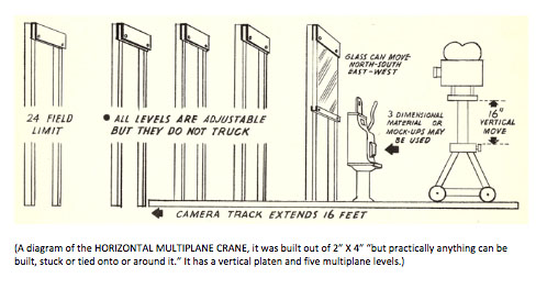
The HORIZONTAL MULTIPLANE CRANE is a variation on the horizontal multiplane camera that Ub Iwerks invented in in 1933 after he had left Disney and started his own cartoon studio. Iwerks built his first multiplane crane with a used camera and parts from an old Chevy.(16) The HORIZONTAL MULTIPLANE CRANE was even more makeshift being built out of 2” X 4” wood studs “but practically anything can be built, stuck or tied onto or around it,” which made this a very versatile camera rig. The manual notes that “the Machine Shop, Carpenter Shop and plenty of Ub’s ingenuity can usually contrive to get an effect or shoot material that stumps the more staid, conventional camera crane.”(17)
The HORIZONTAL MULTIPLANE CRANE has a glass platen, is setup for at least five multiplane levels and can handle backgrounds up to 24 field size, roughly 36-inches by 48-inches. “The camera is not fixed but operates on a dolly and shots horizontally, permitting the use of 3-dimensional models and gadgets that would be impossible on any of the vertically operating cranes.” The standard vertical camera cranes in use at the studio had steel strips with calibration markings and analog counters for accuracy in moving the peg bars, camera tables and cameras. But on the HORIZONTAL MULTIPLANE CRANE there are no calibrations between levels so, when trucking on a level either toward or away from the camera, the needed calibrations are made by the checker on long strips of paper. Those strips of paper are then attached to the tracks for the level being trucked and that level is moved by hand. It was pointless to call for registry between levels on this crane if a truck was called for as the line-up was made only visually through the camera viewfinder. It was also noted that small fields “should be avoided owing to the lack of precision of camera calibration on this crane.”(18)
Although the HORIZONTAL MULTIPLANE CRANE may seem like a kluged together contraption that had to have calibrated strips of paper taped down in order to create a camera move, it was very much a necessity to create certain types of scenes that were not possible on the other animation camera cranes. Think of it as the smoke and mirrors associated with Hollywood film productions. What may appear as Cherry Tree Lane, a street in London, for Mary Poppins (1964) was nothing more than a set built on the soundstages at the Disney Studios lot in Burbank. All that matters is what actually gets photographed onto the film, anything else outside the field of view is irrelevant and never seen by the audience. So it is with how scenes were created for the WWII training films that were made at the Disney Studios during the war years.
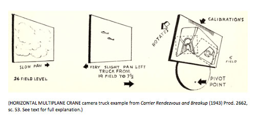
The text gives a great example of a long truck and how it was created on the HORIZONTAL MULTIPLANE CRANE for scene 53 in Carrier Rendezvous and Breakup (1943, Prod. 2662) for the U.S. Navy. The scene was designed to give the impression that the viewer, the “spectator,” is in the cockpit of an airplane. The plane that the spectator is riding in “approaches two others flying in formation. Toward the end of the scene, the single plane [spectator’s plane] banks steeply, bringing its wingtip into the field of vision.” This scene was handled on three levels on the HORIZONTAL MULTIPLANE CRANE. Level one (1) is the sky, “on the 24 field level, which is panned slowly in order to give the 2 distant planes” a sense of forward movement within the scene. The second (2) level has the two airplanes, which are painted on glass. Level 2 is trucked towards the foreground to create the effect that the spectator plane is approaching the two distant airplanes. “This long truck, which continued from a 19 field level to the 7 ½ field level, is possible only on this crane.” Then level three (3), close to the camera and stationary, is the cockpit in the foreground spectator plane that works on a calibrated pivot at a 5 field (Acme 10.5F).(19) This cockpit level was cut out of illustration board and “mounted on a plywood pivot that was bolted to the base” of the stationary wooden frame with the bolt acting as the “pivot point.” The calibration scale was scribed at the top of the illustration board and used for the frame by frame pivot move. Reference the above diagram to help visualize this particular setup and note that this scene could have had additional levels if the layout artists called for it as the HORIZONTAL MULTIPLANE CRANE could accommodate a more complex scene setup.(20)
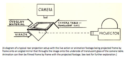
Finally to close out THE CAMERA section of the LAYOUT MANUAL, let’s touch on REAR PROJECTION. The basic principle of rear projections are really very simple in comparison to other camera techniques. Live action or animation, that has already been filmed, is projected onto a mirror that reflects the image up to a translucent screen, typically a piece of translucent glass. On the front side of the screen is a glass camera platen and peg setup that animation can be filmed on against the rear projection screen glass. As the manual states, “when the live action [or animation] film is projected, frame by frame, onto the screen, this image plus the animation is photographed in the normal way to produce the desired combination effect.” So, with a rear projection setup of a live action background, say of clouds and sky, could be combined with one or more animated airplanes. The rear projection setup in the Camera building, on the Disney Studios lot in Burbank, was affectionately known as “Nellie” by the cameramen.(21)

The REAR PROJECTION text uses an example from a film made for the U.S. Navy titled V.T.B. Pilot Training (1943, Prod. 2666), seq. 3, scene 77, which is the pilot’s point of view peeling off and dive bombing an enemy aircraft carrier (the actual text used a derogative term for the enemy).(23) For this scene, “the front of the cockpit remained constant. A long dive was wanted, so the target material—sky, sea, carrier—was painted on 10 field (Acme 23.63F) and shot on the multiplane camera in order to get the very long truck required. Clouds trucking toward the camera on intermediate levels heightened the effect.”(24) Then the print of the camera move on the sky, sea and carrier was projected onto the mirror which reflected it onto the underside of the translucent glass on the camera table platen of the rear projection crane. On top of the camera table platen the cockpit overlay material is then shot, frame by frame, with the sky, sea and carrier that was previously shot projected under it. The final combined effect is the desired point of view from the cockpit dive bombing down through clouds towards an enemy aircraft carrier. When you think about this scene, the animation was completely created between layout and the camera department. There is no traditional animation and the movement created is all done through camera moves on static artwork.
The ability to examine and write about this LAYOUT MANUAL that was used as a reference guide for those Disney artists and technicians who created and, in some case, invented the equipment and techniques is a fascinating window into the mechanics of animation production. So many of the camera “tricks” that were developed during WWII, out of necessity total animation. It is important from an historic standpoint to understand how some of these effects were achieved for no other reason than to have a document of them for posterity.
The next installment in this series will explore the techniques used for filming 3-DIMENSIONAL MODELS and the various techniques used for shooting models, which were heavily used to create inexpensive animation as the Studios turned out a voluminous amount of training films during WWII period.
©David Bossert 2020
 FOOTNOTES
1 – Field Size Comparison Chart: Disney vs. Acme, courtesy Hans Perk.
2 – The 11 FIELD CRANE pages, Layout Manual, Walt Disney Productions, 1943; authors copy.
3 – Iwerks, Don, Walt Disney’s Ultimate Inventor: The Genius of Ub Iwerks; Disney Editions, pg. 57
4 – The 11 FIELD CRANE pages, Layout Manual, Walt Disney Productions, 1943; authors copy.
5 – The author’s personal education, observations and witness to while working on more than thirty Disney
animated features and short films.
6 – he 11 FIELD CRANE pages, Layout Manual, Walt Disney Productions, 1943; authors copy.
7 – Field Size Comparison Chart: Disney vs. Acme, courtesy Hans Perk.
8 – The 11 FIELD LAYOUT pages, Layout Manual, Walt Disney Productions, 1943; authors copy.
9 – The 11 FIELD CRANE pages, Layout Manual, Walt Disney Productions, 1943; authors copy.
10 – The 11 FIELD LAYOUT pages, Layout Manual, Walt Disney Productions, 1943; authors copy.
11 – The 11 FIELD LAYOUT pages, Layout Manual, Walt Disney Productions, 1943; authors copy.
12 – The MECHANICAL CALIBRATOR, Layout Manual, Walt Disney Productions, 1943; authors copy.
13 – The 11 FIELD LAYOUT pages, Layout Manual, Walt Disney Productions, 1943; authors copy.
14 – The 11 FIELD CRANE NOTES, Layout Manual, Walt Disney Productions, 1943; authors copy.
15 – The author’s personal education, observations and witness to while working on more than thirty Disney
animated features and short films.
16 – Pat Williams and Jim Denney (2004). How to Be Like Walt: Capturing the Disney Magic Every Day of Your Life.
HCI. p. 133.
17 – The HORIZONTAL MULTIPLANE CRANE, Layout Manual, Walt Disney Productions, 1943; authors copy.
18 – The HORIZONTAL MULTIPLANE CRANE, Layout Manual, Walt Disney Productions, 1943; authors copy.
19 – Field Size Comparison Chart: Disney vs. Acme, courtesy Hans Perk.
20 – The HORIZONTAL MULTIPLANE CRANE, Layout Manual, Walt Disney Productions, 1943; authors copy.
21 – REAR PROJECTION, Layout Manual, Walt Disney Productions, 1943; authors copy.
22 – REAR PROJECTION, Layout Manual, Walt Disney Productions, 1943; authors copy.
23 – Field Size Comparison Chart: Disney vs. Acme, courtesy Hans Perk.
24 – REAR PROJECTION, Layout Manual, Walt Disney Productions, 1943; authors copy.
 David A. Bossert is an award-winning artist, filmmaker, and author. He received his B.A. from CalArts School of Film and Video with a major in Character Animation. As a 32-year veteran of The Walt Disney Company, he contributed his talents to The Black Cauldron (1985), Who Framed Roger Rabbit (1988), The Little Mermaid (1989), Beauty and the Beast (1991), Aladdin (1992), Tim Burton’s The Nightmare Before Christmas (1993), The Lion King (1995), Fantasia/2000 (1999), and the Academy Award-nominated shorts Runaway Brain (1995), Dali/Disney Destino (2003), and Lorenzo (2004), among many others. Bossert is now an independent producer, creative director, and writer.


I remember that diagram of the horizontal multiplane from “The Illusion of Life” when they were talking about using it for the final shot of Fantasia (that languid shot through a forest at sunrise on the “Ave Maria”), which was only completed mere hours before the world premiere. I assume Iwerks was already back at Disney by then.
Yes, Ub Iwerks returned to the Walt Disney Studios in 1940 where he then stayed for the remainder of his career. He was very instrumental in devising new camera equipment and techniques, especially during the war years, and was awarded many patents.
Actually, before that shot was made for “Fantasia,” the crew constructed a similar horizontal setup for an even more complex scene in “Pinocchio.” This was the opening scene in sequence 2, beginning on the rooftops and moving down into the street and around a corner to Geppetto’s home. The scene took months to plan and execute, and was shot in October-November 1939.
I was always under the impression that the opening scene over the rooftops and down into the village to Geppetto’s home was shot on the upright multiplane camera based on the glass plates the backgrounds were painted on. What are the citations for the horizontal setup being used for that scene?
Hi, Dave – no, that scene was too complex for the standard multiplane crane; the camera moves over the rooftops, down into the street, angles around a corner, and passes under an arch. You’re right, the background elements were painted on glass, but much larger planes of glass than would have been used on the multiplane. To make things even more complicated, some sections of the scene (it was divided into six sections, all of which flow seamlessly on the screen) included animation, which meant that there were also platens mounted upright before the planes to hold the cels in register. All of these elements were mounted on wooden frames at prescribed places along the camera’s path. Herman Schultheis photographed the process at the time the “rehearsal” shot was made in April 1939, and documented it in his famous notebook. You can see those pages reproduced in John Canemaker’s “The Lost Notebook,” on pp182-185. Or you can check it out in Fraser MacLean’s “Setting the Scene,” pp72-75. Or, if you want, you can find it in my book on “Pinocchio,” on pp146-150. The October-November 1939 shooting date for the finished scene is established by the exposure sheets.
Excellent. Thanks for the references.
As you noted, the devices mentioned in this section of the Layout Manual tend to have straightforward descriptive names, like the movable light-box and the mechanical calibrator. But why were those backlit cels called “female masks”?
There are male and female masks. The Female mask is the the silhouette “window” of the object surrounded by black. The male mask is the object painted black with the surrounding area clear. If you used the male and female mask together, you have a completely black field, as they would cancel each other out. Make sense?
Thanks for reading the article.
-Dave
Thank you for the explanation. I did google “female mask” before I wrote my comment, but the results were all about fetish costumes; and when I specified “female mask Disney animation”, it only got weirder.
Just when I thought it was archaic to talk about 35mm, this story pops up! Thanks Dave for writing this!
I think it’s important to note that most of these devices weren’t invented to create scenes, it was the other way around. There were scenes for which they had to engineer a device.
Most of these devices were invented for the WWII training films but they do pop up noticeably in VICTORY THROUGH AIR POWER (of course) and THE THREE CABALLEROS.
To me, the mindset of WDP in the 40’s was to avoid optical printing at all costs even though Linwood Dunn had really perfected it on CITIZEN KANE in 1941.
Most (but not all) of the devices in this story were an attempt to composite in camera and not at later stages on a printer. That’s why they ended up with live action rear projected on an animation camera for THREE CABALLEROS with sub-standard results. By the time MARY POPPINS was produced most (if not all?) photographed effects were composited on an optical printer.
But the description of rear projection may have an omission. The image was usually formed onto ground glass and then above that was translucent glass. You can’t form a rear projected image on a sheet of translucent glass and you can’t use rear painted cels on ground glass, it creates shadows. Interestingly, after Disney abandoned this process, John Oxberry sold a version of it as an option for some of his cameras.
(There is also a way to form the rear projected image onto the focal plane of the camera but I don’t know if WDP ever used this technique?)
I would love to see these devices on display at a museum alongside a 4K monitor with the scenes they were used in. (Please not in Florida. Can’t we have an animation museum here in L.A?)
The quote, that the “layout man should not call for smaller moves than he could reasonably expect to make himself—were he working on the crane” and the strips of paper used on the horizontal multiplane, really ring true.
In camera we would sometimes be asked to break down (say rotational degrees) below 1/10 of a degree and beyond (which I could do with a yardstick attached to the camera bed and huge sheets of paper to mark the positions.
And Dave, you may want to check for photos of the horizontal multiplane used in SLEEPING BEAUTY. By that time I think they had Veeder root counters geared to the track! How’s that for archaic?!
Hi David,
Appreciate you reading the article and for your comments. I agree with your comment, “most of these devices were invented for the WWII training films.” Yes, because they were such thin budgets on those films they really had to be inventive to get the best quality and still keep costs down. I value your input above.
Thank you,
-Dave
A correction! Translucent glass is the same as ground glass so long as the rough side faces down towards the projector and the smooth side faces up towards the bottom of the cel!