

THE CAMERA department is one of the most vital functions of the animation process because without it, how would audiences be able to view the films. The animated scenes that make up a film come together as the finished visuals in the camera department where the painted cels, backgrounds and special effects, both drawn and optical, all meld together after being photographed onto film. The opening text in this chapter of the LAYOUT MANUAL states, “Our best friend in this business is the camera. Properly handled, it will jump through hoops, as the saying goes. Its collection of pegs, bars and camera moves, dissolves, and fades, intelligently directed, makes it an instrument as flexible as an acrobat, as ready to achieve drama as Orson Welles with a hatful of rabbits, as anxious to eliminate animation as a surgeon after a tonsil.”(1) In other words, the cartoon camera and stand in combination with artwork and thoughtfully planned out scenes can actually achieve robust visuals for storytelling quickly and at a minimal cost.
This is only true though when it is in the hands of experienced artists and technicians. It is just as easy to make a scene more complicated, time consuming and thereby much more costly in the hands of an inexperienced person. This has been the case on many animated productions over the decades, a simple scene becomes convoluted and complex requiring more time by the various departments in the animation process then if it was planned more efficiently. That complexity rachets up the costs in a disproportionate amount to other similar scenes done in a more intelligent and thoughtful fashion.(2)

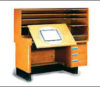
THE CAMERA chapter starts out with the most basic camera setup known as the “standard crane.” This is a simple structure composed of a fixed table with moveable camera situated above it. The standard camera at the Disney Studios had the ability to, under the Disney field guide system, to handle 5 field to 6 ½ field material. That translates into the Acme standard fields of approximately 10.5F to 14.5F.(3) So, the standard crane could handle animation on 12F to 16F paper or cels.
A “field” is the viewable area— what would be photographed onto film under the camera. Like the peg system mentioned in The Layout Manual Part 1, the Disney Studios had their own field guide system that was different from the Acme standard used by the rest of the animation industry. The Disney field guide system was in use until 1985 when the Studios changed over to the Acme standard system at the outset of production on Disney’s The Great Mouse Detective (1986).
The standard crane can move, or truck-in, from the widest 6 ½ field (Acme 14.44F) to the smallest 2 ¾ field (Acme 4.59F)(4). Moving any closer could cause the glass platen, when open, to hit the camera. The camera on the standard crane has the ability to move “East and West or North and South, or a combination of the two for angular moves” and can rotate up to a full 360 degrees.5 Hence the fixed table top that holds the artwork. What might appear as the artwork moving is actually the camera moving above the art.
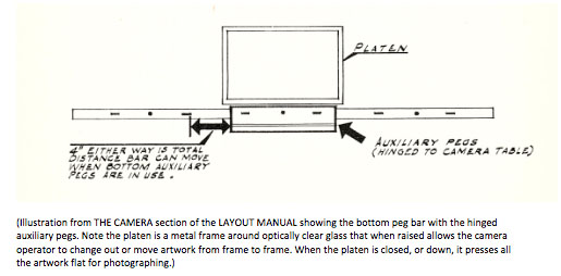
The sliding peg bars on the fixed table are calibrated to 1/100” and up allowing for incremental panning of background elements or sliding cels. The WWII training films utilized these functions frequently as it was an inexpensive way to create animation at a low cost. The top and bottom peg bars could move under the animation levels on the fixed pegs up to 4-inched on either side. It was possible to get a greater panning or sliding cel range out of the top and bottom peg bars by removing the actual pegs and taping the artwork to the bar itself. Although, this was not recommended and “should be avoided if possible” (6) because artwork not on pegs, even if taped down, could shift and go out of registration. The purpose of the peg system is to keep all the artwork in registration in order to maintain smooth action of the animating elements.
The standard crane had the ability, for normal set-ups, to use 4-levels of cels “although more can be used under exceptional circumstances,” as noted in the manual. Typically the maximum amount of cels, stacked on top of a background, that should be used is four, if you use any more than that the color and color values of the animation and background will be “seriously affected.” Essentially what happens when you stack cels is that the collective density of the cels will begin to darken the underlying artwork. This is commonly seen in pre-computer age animation when characters change levels during the course of a scene.
Have you ever noticed an animated character appear to pop lighter or darker while watching an animated film? This happens when the character switches from one cel layer to another, within the four cel layer stack, without the paint value being compensated for. At the Disney Studios, because they made their own paint, there were value differences of each paint color that were used specifically when a character had to be moved from one cel level to another. The paint value took into account that level change and therefore avoided the “pop,” either slightly lighter or darken, when the level change occurred. In other words, the character is painted with one paint color and then upon the level switch the paint color is changed to a value higher or lower based on how the level change is planned, thus keeping the paint color consist and the level change imperceptible to the viewer.(7)(8)
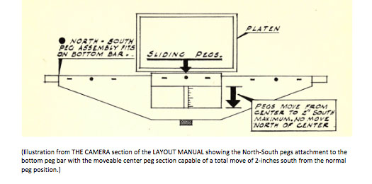
It was possible to do a north-south move of artwork on the standard crane using a special engineered peg attachment. By clamping the north-south movable pegs to the bottom peg bar, the animation or still art layer could then be moved up to a maximum range of 2-inches south. It could not go north as the pegs would either prevent the platen from closing fully or actually break the platen glass. Now, it is possible to give the appearance of a greater north-south move with the use of a north truck of the camera to augment the south peg move. While the artwork is moved incrementally south per-frame, the camera can be moved incrementally north per-frame, which will give the viewer the illusion of greater overall movement.
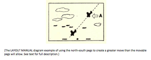
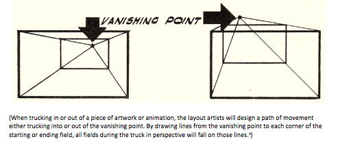
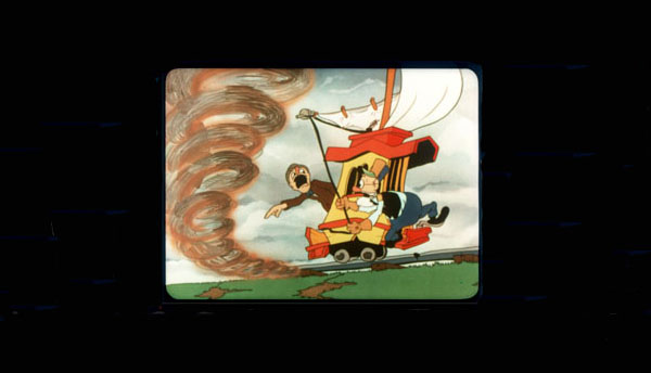
The LAYOUT MANUAL text gives the following example, “Let us say the subject is an airplane diving through a formation of planes and clouds moving in a horizontal direction [see above diagram]. Lay out the complete dive path required. The north-south peg move will permit only a fraction of the total; say, down to A, –at that point the pegs will be at their maximum south position. Trace the plane in this position on cel in maximum north position, repeating process throughout the scene. Thus, plane can move from border to border of field using the north-south pegs.” The manual does advise not using the full range of movement, but rather “leaving some leeway for registration.” The use of the north-south technique was extensive in the training films made at the Disney Studios as it was an economical way of getting a higher level of quality while still keeping costs under control.(9)
Another venerable function is using the camera truck to create the illusion of animation. A camera truck is merely when the camera trucks in, moves closer, or trucks out, moves away, from a piece of stationary artwork on the fixed table. It can give the effect of motion, i.e. moving in, out or past on an object or background element. Used in combination with a sliding cel or simplistic animation it can be very effective in giving the impression of higher quality “animation” without the associated costs.
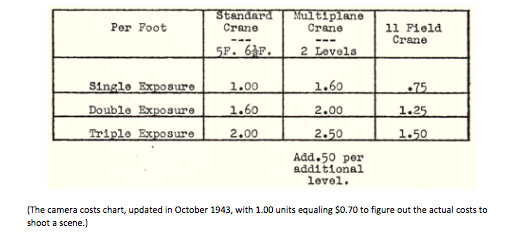
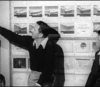
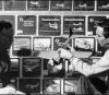
The LAYOUT MANUAL does cover costs in broad terms, which is unusual since most artists and technicians, as a rule, are typically kept in the dark about the actual costs involved in creating animated films at Disney. During the latter part of the 20th Century at The Walt Disney Animation Studios, the philosophy was that the artists should not have to worry about costs and instead just focus on creating the films while letting production management bear the burden of managing the costs.(11) But within THE CAMERA section there is a sheet titled CAMERA COSTS that breaks down and compares average costs between the standard crane, the multiplane crane (using two levels) and the 11 Field crane.(12) The document states, “As a general rule, multiplane averages two to three times more than the standard crane.” The multiplane camera required more than one cameraman to operate, for complex scenes, like the opening shot through the Bavarian village in Pinocchio (1940), it used as many as eight or more cameramen to film that scene.(13) The CAMERA COSTS page appears to have been updated in October, 1943, as indicated by the cost per unit, with 1.00 units equaling $0.70.(14)
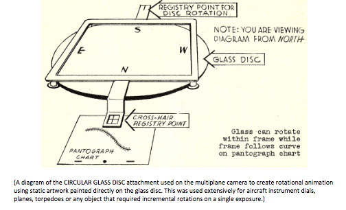
The cost associated with using the multiplane camera to its fullest extent were prohibitive for use in the tight budget training films. But, a development for the multiplane camera that came about through the creation of “instructional pictures” is a device known as the CIRCULAR GLASS DISC. It was designed to be used for most rotational work being done as one exposure—meaning artwork is photographed at 100% on each frame. As an example, the circular glass disc was used for moving static artwork such as a plane, compass gauge or having held art of say a torpedo that is flying horizontal begin to tip down as it drops. The artwork would be painted directly on to the glass of the circular disc in a similar fashion to how overlay and background elements were painted directly onto the optical glass plates on the various levels of the multiplane camera rig. The disc was able to move “north, south, east and west, by either a pantograph or counter-movement, or both, besides trucking toward and away from camera, from 2 ½ Field to 9 ½ Field (Acme 4F to 22.31F)(15), and can rotate around its own center.” The CIRCULAR GLASS DISC worked on any level of the multiplane camera but because the artwork is painted directly on the glass and there are no pegs, it could not use animation or other art on cels on the same level. It was, however, possible to use two of the glass discs at one time.(16) This was a time and money saving device that was used in countless training films throughout the war years at the Disney Studios.
 Another device, the DIAL GAG, was developed for the multiplane camera that allowed for “one or more dials, cog wheels, needles, etc.—such as a dashboard instrument panel” that needed to move. The document refers to it as doing “a right smart job.” The device permitted the use of a rotation speed slower than is practical with drawn animation. The DIAL GAG device was able to do up to three dials at once and the multiplane department had a supply of stock metal arrows and gage needles, which were made at the Studios Machine Shop. The DIAL GAG was used for several needles in the training film Icing Conditions (1942), Prod. 2623, for the U.S. Navy among many others.(17)
The document makes the somewhat ominous note to, “always check with Multiplane Planning before starting to work on a multiplane scene, particularly where registration from level to level is involved.” As much as the multiplane camera could produce spectacular scenes, it could also be costly in the hands of an inexperienced artist.(18)
Under GENERAL NOTES, there are listed four entries that were helpful to keep in mind when planning a scene, they are: 1) Don’t have a held cel between two sliding cels— liable to twist and stretch due to static attraction. 2) Keep airbrush cels on top level whenever possible. 3) When having short cycles to be used many times, make several sets—particularly if they are in airbrush. They get scratched and chipped. 4) Avoid double exposure during a truck. It is next to impossible to match the truck exactly. Better use an extra cel on first exposure if exactness is desired.(19) These are very succinct points that the layout artist, checkers and cameramen had to keep in mind to avoid a problem cropping up at a critical moment when filming the animation is underway. For instance, when using a short cycle many times, aside from potential scratches and chipped paint, the peg holes can begin to stretch through repeated use or are susceptible to tearing through normal wear and handling, which will introduce registration issues creating an undesirable shake or bump to the animation.
The next installment will examine the 11 FIELD CRANE development that allowed for the use of “other kinds of material than could be used on the multiplane crane” that needed to move.(20) The device was invented by Ub Iwerks and allowed for more inventive uses of the camera for the WWII training films.
©David Bossert 2020
Footnotes
1 – THE CAMERA text, Layout Manual, Walt Disney Productions, 1943; authors copy.
2 -The author’s personal observations and witness to while working on more than thirty Disney animated
features and short films.
3 – Field Size Comparison Chart: Disney vs. Acme, courtesy Hans Perk.
4 – Field Size Comparison Chart: Disney vs. Acme, courtesy Hans Perk.
5 -Layout Manual , Walt Disney Productions, 1943; authors copy.
6 – THE CAMERA text, Layout Manual, Walt Disney Productions, 1943; authors copy.
7 – The author’s personal education, observations and witness to while working on more than thirty Disney
animated features and short films.
8 – Layout Manual , Walt Disney Productions, 1943; authors copy.
9 – THE CAMERA text, Layout Manual, Walt Disney Productions, 1943; authors copy.
X – THE CAMERA text, Layout Manual, Walt Disney Productions, 1943; authors copy.
11 – The author’s personal education, observations and witness to while working on more than thirty Disney
animated features and short films.
12 – CAMERA COSTS page, Layout Manual, Walt Disney Productions, October,1943; authors copy.
13 – Evidenced by examining multiplane camera photos from that time period.
14 – CAMERA COSTS page, Layout Manual, Walt Disney Productions, October, 1943; authors copy.
15 – Field Size Comparison Chart: Disney vs. Acme, courtesy Hans Perk.
16 – MULTIPLANE CRANE page, Layout Manual, Walt Disney Productions, 1943; authors copy.
17 – DIAL GAG page, Layout Manual, Walt Disney Productions, 1943; authors copy.
18 – DIAL GAG page, Layout Manual, Walt Disney Productions, 1943; authors copy.
19 – GENERAL NOTES page, Layout Manual, Walt Disney Productions, 1943; authors copy.
20 – 11F Crane page, Layout Manual, Walt Disney Productions, 1943; authors copy.
 David A. Bossert is an award-winning artist, filmmaker, and author. He received his B.A. from CalArts School of Film and Video with a major in Character Animation. As a 32-year veteran of The Walt Disney Company, he contributed his talents to The Black Cauldron (1985), Who Framed Roger Rabbit (1988), The Little Mermaid (1989), Beauty and the Beast (1991), Aladdin (1992), Tim Burton’s The Nightmare Before Christmas (1993), The Lion King (1995), Fantasia/2000 (1999), and the Academy Award-nominated shorts Runaway Brain (1995), Dali/Disney Destino (2003), and Lorenzo (2004), among many others. Bossert is now an independent producer, creative director, and writer.


Hello David!
Fascinating article! This version of the manual may have been how management wished things worked but actual practices may have differed.
The most glaring error are the cost differentials between a standard crane vs. multiplane. All the multiplane price quotes seem optimistic at best.
You wrote: “It was possible to do a north-south move of artwork on the standard crane using a special engineered peg attachment.” These were called “North & South pegs”. I found that the best way to explain this device is to refer to any car in a Hanna-Barbara production in the 60’s: “You know that little bump the cars would do while the bg is panning? That’s North & South pegs.”
Another name for this device was a “Crossbow” when some rotation was added (probably years after this manual). The North South pegs could rotate to a slight angle while the camera bed (or camera) remained at 0 degrees. This was much cheaper than the circular glass disc method.
It should be noted that Disney had one camera which could shoot oversized underlit shots for pencil tests. I think it was an equivalent of an Acme 18 field but I only had 16 field shot on it (for Brad Bird’s “Family Dog”). Supposedly, this camera was used a lot for Tinkerbell’s shots in “Peter Pan” (where she was small in frame and her glow needed to be underlit). Yes, cameras were cast like actors!
Yours,
David Koenigsberg
Hi David,
Yes, I agree with you on the costs differences between the standard crane and the multiplane cameras. Even with limiting the multiplane to two levels, it was still more expensive to operate.
Thanks for you input on the North/South pegs. There are plenty of examples in the H&B cartoons.
The 18F camera you mentioned may have come after the WWII era as there is no mention of it in the LAYOUT MANUAL.
Glad you enjoyed reading the piece.
Thank you,
-Dave
Pity the poor camera operator in an animation studio. As important as his job is, the quality of his work only gets noticed when he makes a mistake!
It must have been a steep learning curve to work out camera technique in the early days of animation. There are quite a lot of obvious layout errors in old cartoons: cels missing, in the wrong place or the wrong order, etc. A particularly glaring one occurs in the 1929 Mickey Mouse cartoon “The Plow Boy”, where the background pans in the wrong direction behind a walking cow, giving the impression that she is doing some sort of backwards Michael Jackson Moonwalk!
I’m enjoying your articles about the Disney Layout Manual. I have a basic knowledge of how cartoons were made in this era, but this information is more detailed than anything I’ve read. I was impressed to learn that Disney created different shades of paint to compensate for cel placement. That is an extraordinary level of quality control.
LOL! I couldn’t agree more. The camera operators were only noticed if there was a mistake. I appreciate your note and glad you are enjoying the articles on LAYOUT MANUAL.
Dave,
Really enjoyed Parts 1 and 2, especially the latter. It’s amazing how innovative Disney was in moving animation forward from rather rudimentary beginnings to “where no man has gone before,” to quote Star Trek. It was not only the artists, who got better and better at creating the illusion of life, but the camera and camera operators who most folks don’t even thing about. After all, Walt’s nine old men weren’t known for their work as camera operators…and would they have become as highly regarded without those operators.
Thanks, and keep ‘em coming.
Jim